Campagnolo Delta Brake Setup
from Toe Clips Summer `94
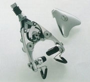 The following is a worksheet for the Delta brake. The brake has a reach range of 35 to 47mm, which makes it a “short reach” type. The internal linkage operates like a “scissors jack” and is quite powerful. The linkage is held together by C-clips, but disassembly is usually not necessary and is a pain in the neck. Clean the internal parts as a unit with solvent, dry with compressed air and lubricate all pivots with alight oil. The caliper housing will limit the selection of tire use. Large cross section tires may end up very close or may even contact the brake housing. The cables fray upon securing, so count on installing a new one rather than reusing the old cable.
Installation
 Loosen brake pad bolts and lubricate threads. Set brake pads to lowest position in the caliper arms. Apply Locktite #242 to caliper mounting bolt or sleeve nut.
- Install caliper to frame and secure to mounting but to snug. Center caliper arms to rim. Centering of caliper arms will not affect pad alignment.
- Set pad height by loosening brake mounting nut and moving entire caliper up or down. Set brake pads at the lowest edge of braking surface. Align pads tangent to rim, secure to 60 inch pounds. Hold caliper centering to rims and secure mounting nut to 70 inch pounds. Double check pad alignment.
- Size and finish cable housing.
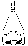
- Remove cover plate by squeezing pads together and lifting up on top cap which is beneath adjusting barrel spring. Lift off cover plate. Remove adjusting barrel and lubricate threads.
- Reinstall and turn clockwise until it bottoms out, then turn counter clockwise 3-4 turns.
- Hold the cable pinch nut with a 9mm open end wrench, and loosen cable pinch set screw with a 9/64″ Allen key.
- Lubricate threads of cable pinch set screw. Oil inside of housing of exposed cable from 2.5 to 3.5 inches from end of housing. The cable tends to fray when cable pinch mechanism is secured. Take care to solder the section without lumps of solder.
- Feed cable through barrel adjuster and through hole in cable pinch mechanism. The hole is hidden behind the internal brake linkage. Cable pinch nut wrench flat will be at approximately 10:00 position.
- Hold the pads to the rim with a 3rd hand. Pull downward of the cable to remove stack in cable. A 4th hand is not necessary. Secure the cable pinch set screw to equivalent of 50 inch pounds. It is not necessary to maintain cable tension while securing set screw. Remove the 3rd hand tool.
- Stress the cable systems by pulling on the lever the equivalent of 10 panic stops.
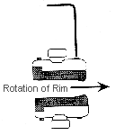
- Set clearance of the pads to the rim using the barrel adjuster. Measure each side separately with a stack of feeler gauges for clearance.
- Remove the wheel. Squeeze the pads as fully closed as possible. This raises the cable pinch mechanism above the bottom of the caliper housing. Cut the cable as close to the cable pinch mechanism as possible. The cable is likely to fray at this time.
- Allow the pads to return to their normal position. If the end of the cable is clearing the caliper housing, it is short enough. If the cable is resting on the housing, attempt to cut it shorter using a quality pair of diagonal cutters.
- Reinstall caliper cover and install wheel. Center brakes so that pads
 strike rim simultaneously. To fine tune pad centering, loosen mounting bolt, move and hold caliper body, and then secure mounting nut. Double check pad alignment after changing centering. Fine tune moving only pads, not caliper arms.
 - Clean rim with acetone or similar solvent. If brakes squeal upon test ride, toe pads by means of the front set screw in the pad holder. Use care not to displace pad from holder.
Written By Calvin Jones